Capacitor Test on the Teradyne TestStation InCircuit System
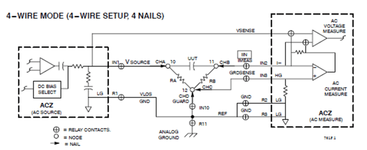
The ACZ unit makes capacitance measurements. This unit applies an AC source voltage to the source node of the component-under-test and measures the in-phase and quadrature components of the voltage across the component and the current through it. The system software then uses these measured values to calculate the actual capacitance.
The SET MUX statement for ATG--generated capacitor tests is:
SET MUX AT (CHA=ACZVSRC: CHB=ACZIMEAS: CHC=ACZGRDSNS:
CHD=REFCONN: REF=ACZGND,ACZGND2,ACZGND3,ANAGND);
Channel Connection
- CHA AC Voltage Source
- CHB AC Current Measure
- CHC AC Measure Guard Sense
- CHD Reference Connection
- REF ACZVSRC,ACZIMEAS,ACZGRDSNS, and ANALOG GROUNDS
Test Set-up for Capacitance Measurement (4-wire mode)
A single measurement unit, the ACZ, is used for measurements of capacitance. Because only one instrument is involved, ATG is able to exploit the measurement capabilities more thoroughly than can be done for DC measurements, and there is generally less room for you to try other measurement techniques.
Debug Techniques
If measurements are unstable, there is usually a guarding problem. Components surrounding the DUT can provide an undesirable shunt path which permits current to flow around the DUT and affects the measurement. Properly guarding low value impedances results in good measurements.
Capacitor Test on the Keysight 3070 InCircuit Tester
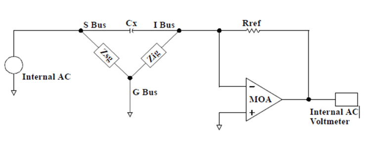
The capacitor test measures capacitance from 10 pF to 10,000 UF.
Test Configuration
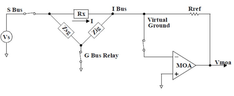
The capacitor under test is connected in the input path of the MOA as shown below. An AC source is applied to the device under test, and the output of the MOA (Measuring Operational Amplifier) is measured with an AC voltmeter.
Guarding (G Bus)
The device under test may have one or more parallel impedance paths due to the circuit topology of the board under test. These parallel impedance paths cause measurement errors by providing current paths around the component under test. Zsg and Zig, in diagram below, represent the components forming parallel impedance paths around the component under test, Rx.
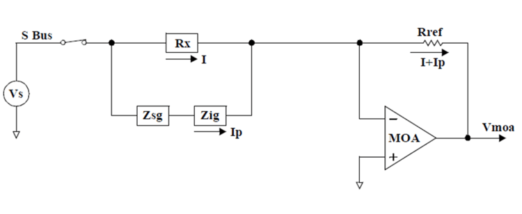
The G bus is used to guard the component under test by breaking parallel impedance paths. The diagram below shows where the G bus is connected in the circuit when the component under test is shunted by a parallel impedance path. By connecting the G bus as shown, the current that would flow through both Zsg and Zig becomes insignificant.