Integrating NI LabVIEW, High-Resolution Camera System, Barcode Scanner, and Custom DUT Interface for ECU Validation
CONTENTS
- Test Objectives
- The ECU
- Solution Overview
- Required Tests
- System Interface Connections
- Test Sequence
- Test Program Execution
1. TEST OBJECTIVES
Ensure that each product leaving the production line meets the required quality standards, specifications, and functions correctly to operate according to the design specifications.
2. THE ECU
The Driver Alert System ECU supports one LIN (Local Interconnect Network) channel. It controls LED lighting based on input signals from the ADLM (LIN Master), ensuring seamless integration and reliable performance within the vehicle's electronic architecture.

3. SOLUTION OVERVIEW
Acculogic developed a comprehensive end-of-line functional tester to validate electronic control units (ECUs) for input/output functionality, identification protocols, and diagnostic capabilities. This turnkey solution integrates:
- NI LabVIEW ADE (Application Development Environment), a powerful graphical programming platform that enables the creation of custom test software with a wide range of built-in functions for data acquisition, instrument control, and test sequencing.
- High-resolution camera system to verify the presence, placement, and functionality of LEDs.
- Barcode scanner for rapid and accurate identification of the ECU under test. By scanning the barcode on the ECU, the tester can automatically retrieve relevant information such as part numbers, serial numbers, and test parameters from a database. This feature enhances the traceability and data integrity of the test process, ensuring that each ECU is tested against the correct specifications and that the results are properly logged and associated with the specific unit.
- The Bed of Nails (BON) DUT interface is custom-designed to accommodate the specific form factor, connector types, and pinout of the ECU. This interface ensures reliable and repeatable connections through high-quality pogo pins and sockets between the ECU and the test system, minimizing the risk of connection errors or damage to the unit under test. Premium probes and sockets ensure excellent electrical contact, reduced wear and tear, and increased durability, resulting in a more stable and consistent testing process. The DUT interface also incorporates necessary protection circuitry, such as electrostatic discharge (ESD) protection and overcurrent protection, to safeguard the ECU and the test equipment during testing.


4. REQUIRED TESTS
Acculogic's automated test solution validates the Driver Alert System ECU through an extensive set of functional test cases to ensure compliance with design specifications and performance requirements.
- Reverse Polarity Test: This test ensures that the ECU is protected against reverse polarity connections, which can cause damage to the electronics. The test fixture should include provisions for safely applying reverse polarity and monitoring the ECU's response.
- ECU Current Consumption Test (When LEDs are OFF): Measuring the ECU's current consumption when the LEDs are off helps to verify that the unit is not drawing excessive current in its idle state. This test can be performed using a precision current measurement device, such as an NI DMM.
- Identification Data Readout Tests: These tests validate the ECU's identification data, such as part numbers, serial numbers, and software versions. The test system can request and verify this data against expected values using the LIN communication channel.
- Battery Measurement Tests: Validating the ECU's ability to measure the vehicle's battery voltage accurately is critical for proper operation. The test fixture should include a programmable power supply to simulate various battery conditions, and the test system can verify the ECU's battery measurement accuracy.
- Binning information of ECU vs. production database: Comparing the ECU's binning information against the production database ensures that the correct software and calibration data are programmed into each unit.
- LEDs Test based on Vision Inspection with Camera: A high-resolution camera system can be used to inspect the LEDs' functionality, color, and placement.
- LEDs Intensity measurement in lumens: Measuring the LED intensity in lumens ensures that the LEDs meet the specified brightness requirements.
- LEDs current consumption in various LED branches: Monitoring the current consumption of individual LED branches helps to identify any anomalies or defects in the LED circuits.
- LEDs DC-DC Voltage Measurement Test: Verifying the voltage levels of the LED driver circuits is essential for proper LED operation. The test system can measure these voltages using an NI DMM or a custom signal conditioning board.
- Temperature Tests: Subjecting the ECU to various temperature conditions ensures it operates reliably across the specified temperature range. An environmental chamber can be integrated into the test system to perform these tests, with the test fixture designed to withstand temperature variations.
5. SYSTEM INTERFACE CONNECTIONS
The test system's architecture, as illustrated in the diagram, consists of a fixture and a computer equipped with various modules and interfaces to facilitate comprehensive functional testing of the Driver Alert System ECU.
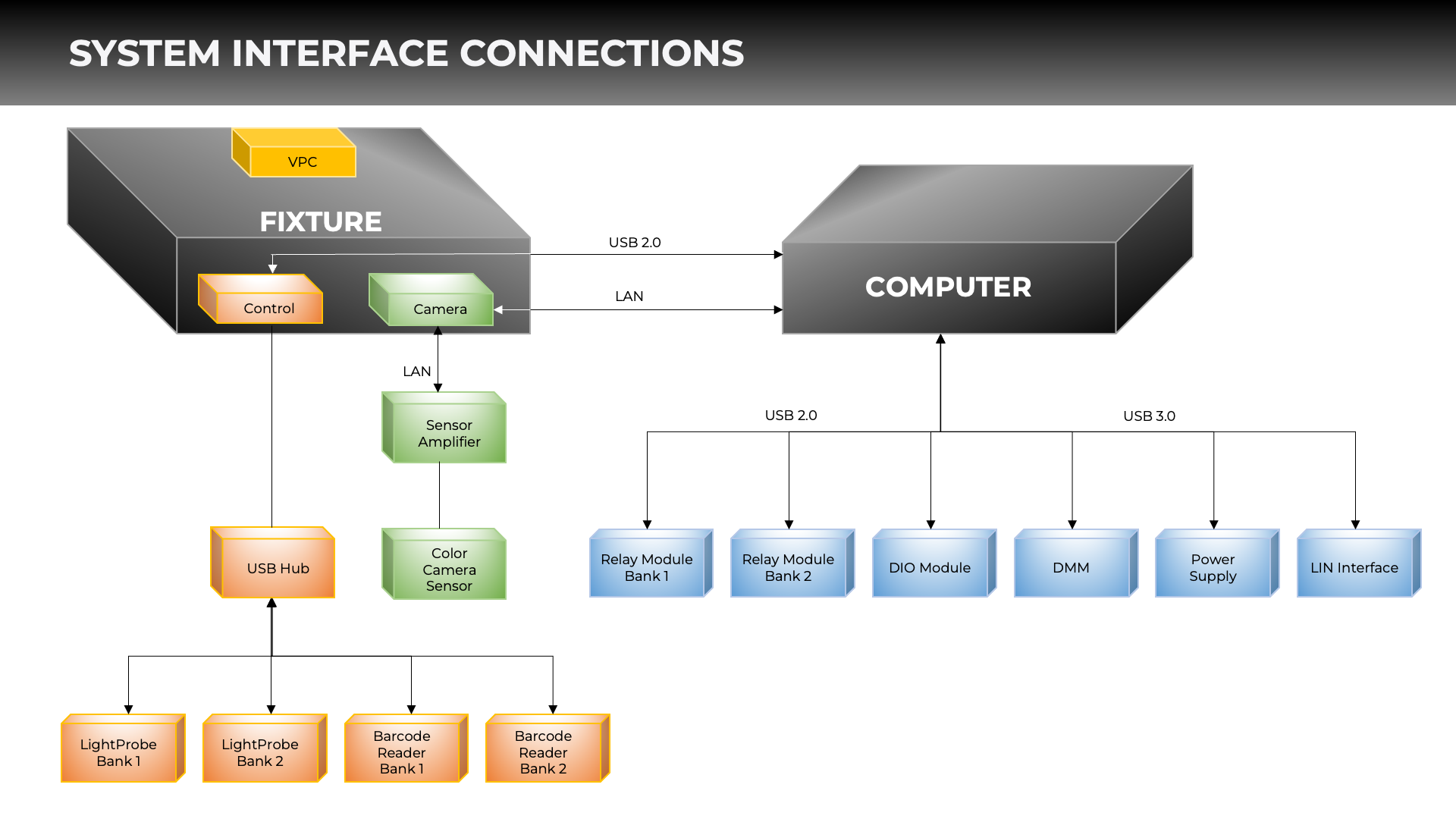
The fixture comprises a control unit, camera, and sensor amplifier, which are essential for executing the test cases and capturing the necessary data. The control unit manages the overall operation of the fixture, while the camera is used for optical inspections and measurements. The sensor amplifier conditions and processes signals from various sensors within the fixture.
The fixture is connected to the computer through a USB hub, which serves as a central point for connecting multiple devices. The USB hub establishes communication between the fixture's control unit, camera sensor, and the computer, enabling seamless data transfer and control.
The computer is equipped with several modules and interfaces that play crucial roles in the testing process:
- Relay Module: These modules allow the computer to control relays for switching signals and power during testing. By manipulating the relays, the test system can simulate different operating conditions and test the ECU's response to various input combinations.
- DIO (Digital Input/Output) Module: This module enables the computer to send and receive digital signals to and from the device under test (DUT). It facilitates the testing of the ECU's digital interfaces and ensures proper communication between the ECU and other components in the system.
- DMM (Digital Multimeter): The DMM module enables the computer to perform various electrical measurements on the DUT, such as voltage, current, and resistance. These measurements are critical for verifying the ECU's power consumption, signal integrity, and compliance with electrical specifications.
- Power Supply: The power supply module provides the necessary power to the DUT and other test equipment. It ensures a stable and consistent power supply throughout the testing process, mimicking the ECU's operating conditions within the vehicle.
- LIN (Local Interconnect Network) Interface: This interface facilitates communication between the computer and the DUT using the LIN protocol, which is commonly used in automotive electronics. It allows the test system to send commands, receive responses, and monitor the ECU's behavior on the LIN bus.
In addition to the modules directly connected to the computer, the diagram shows four separate devices connected to the USB hub:
- LightProbe Bank: These devices are used for light stimulus during testing. They enable the test system to evaluate the ECU's response to different lighting conditions and ensure proper functionality of the LED control circuitry.
- Barcode Reader: These devices are used for scanning and retrieving information from barcodes on the DUT.
6. TEST SEQUENCE
The automated end-of-line functional tester follows a comprehensive test sequence to ensure that the Driver Alert System ECU meets all the required specifications and functions correctly. The test sequence includes the following steps:
- ECU is mechanically locked in the interface with disabled power supply and no active communication. This ensures that the ECU is securely positioned and isolated from any electrical or communication signals during the initial phase of the test sequence, preventing any unintended interactions or damage to the unit.
- Application automatically senses which DUT section is active and ready for testing. The tester detects the presence of an ECU in the test fixture.
- The barcode reader scans the 35-character DMC code on the ECU, enabling the tester to identify the ECU accurately, apply the correct test specifications, and validate various aspects of its functionality throughout the testing process.
- Perform Reverse Polarity test verifies that the ECU is protected against accidental reverse polarity connections that can cause severe damage to the electronic components.
- Validate the current consumption when all LEDs are in OFF condition. This test measures the ECU's quiescent current draw when none of the LEDs are active, verifying that it meets the specified limits. Excessive current consumption in the OFF state can indicate potential issues with the ECU's power management or circuit design.
- Perform diagnostic tests on the ECU using LIN communication to validate the identification data with the DMC code. The tester establishes communication with the ECU using the LIN protocol and retrieves various identification data, including:
- Software Version: Verifies that the correct software is programmed on the ECU and matches the expected version.
- Hardware Version: Ensures the ECU's hardware revision is compatible with the specified requirements.
- Serial Number: Validates the unique serial number assigned to the ECU by the manufacturer.
- FCA Part Number: This confirms that the ECU's part number matches the one specified by the customer for the vehicle application.
- Module Number: Checks the module number to ensure compatibility with the vehicle's electrical architecture.
- Perform Battery Measurement Diagnostic tests on the ECU to check its performance at different battery voltages, including extreme limits.
- Perform LED Binning Information Readout Diagnostic Tests on the ECU using LIN communication and compare the retrieved values to the ones in the production dataset corresponding to the Bin information on the DMC code for Red, Green, and Yellow LED Bins. This test verifies that the LEDs used in the particular application or product are consistent in their performance and meet the desired specifications and quality standards.
- Conduct LED Tests:
- Switch ON Red LEDs at 100% intensity while keeping Green and Yellow LEDs at 0%. Use a camera and vision inspection algorithms to check whether all the Red LEDs are glowing correctly. Measure the intensity of the Red LEDs and compare it with the intensity requirements.
- In this condition, measure the current in Branches 1 through 4 for the Red LEDs and the DCDC Voltage. Compare these values with the limits configured based on the LED Bin information.
- Repeat the same steps to check the green and yellow LEDs in sequence.
- Perform the DC-DC Test again when all the LEDs are at 0% intensity and compare the results with the configured limits. This test ensures that the ECU's power management system functions properly and maintains the desired voltage levels even when the LEDs are inactive.
- Conduct Temperature Tests to measure the Chip and Board temperatures and verify that these values are within the expected range, typically around room temperature. This test helps identify potential thermal issues that could affect the ECU's performance or reliability.
- Initiate ECU Shutdown by stopping all LIN communication with the ECU and turning off the power supply. This step ensures a controlled and safe termination of the testing process, preventing any unintended interactions or damage to the ECU.
7. TEST PROGRAM EXECUTION
Application Launch and Hardware Communication:
- The application establishes communication with all connected hardware components upon launch.
- Successful communication allows the software to control and interact with the hardware devices.

Operator Interaction and Instrument Control:
- The system provides an intuitive user interface for the operator to interact with stand-alone instruments and devices.
- The operator can configure instruments, apply stimuli, measure, and acquire data from the ECU.
- The operator can adjust parameters, initiate tests, and monitor test execution progress.


The Barcode Scanner reads the DMC Code from ECU in the Bank currently under test.
The segregated Identification parameters are compared with the Diagnostic Identification Data Readout parameters.

The tester performs Battery Measurement Diagnostic tests on the ECU using LIN communication to check its performance at different externally applied battery voltages, including extreme limit

The system performs LED tests on the ECU using LIN communication to check the performance of various LEDs available on the ECU and their associated parameters.

The system performs DC-DC, Chip & Board Temperatures Diagnostic tests using LIN communication to check the ECU's performance when the LEDs are in the OFF condition and to validate the temperature sensors on the ECU.


Acculogic's end-of-line functional tester for the Driver Alert System ECU integrates NI LabVIEW, high-resolution camera systems, barcode scanners, and custom DUT interfaces. This comprehensive test solution offers a streamlined and efficient approach to ECU validation.
The modular architecture, intuitive user interface, and features such as automatic ECU detection and comprehensive test reporting further enhance the efficiency and traceability of the testing process.
Automated test solutions like Acculogic's end-of-line functional tester play a vital role in ensuring vehicle safety, reliability, and performance on the road.