
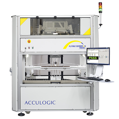
SCORPION FLS980Dxi Semiconductor Load Board Testing
Ensuring Quality Through Comprehensive Load Board Testing.
 Configurable to meet your unique needs
Unequalled test coverage
Superior component access
Soft touch probing
Configurable to meet your unique needs
Unequalled test coverage
Superior component access
Soft touch probing
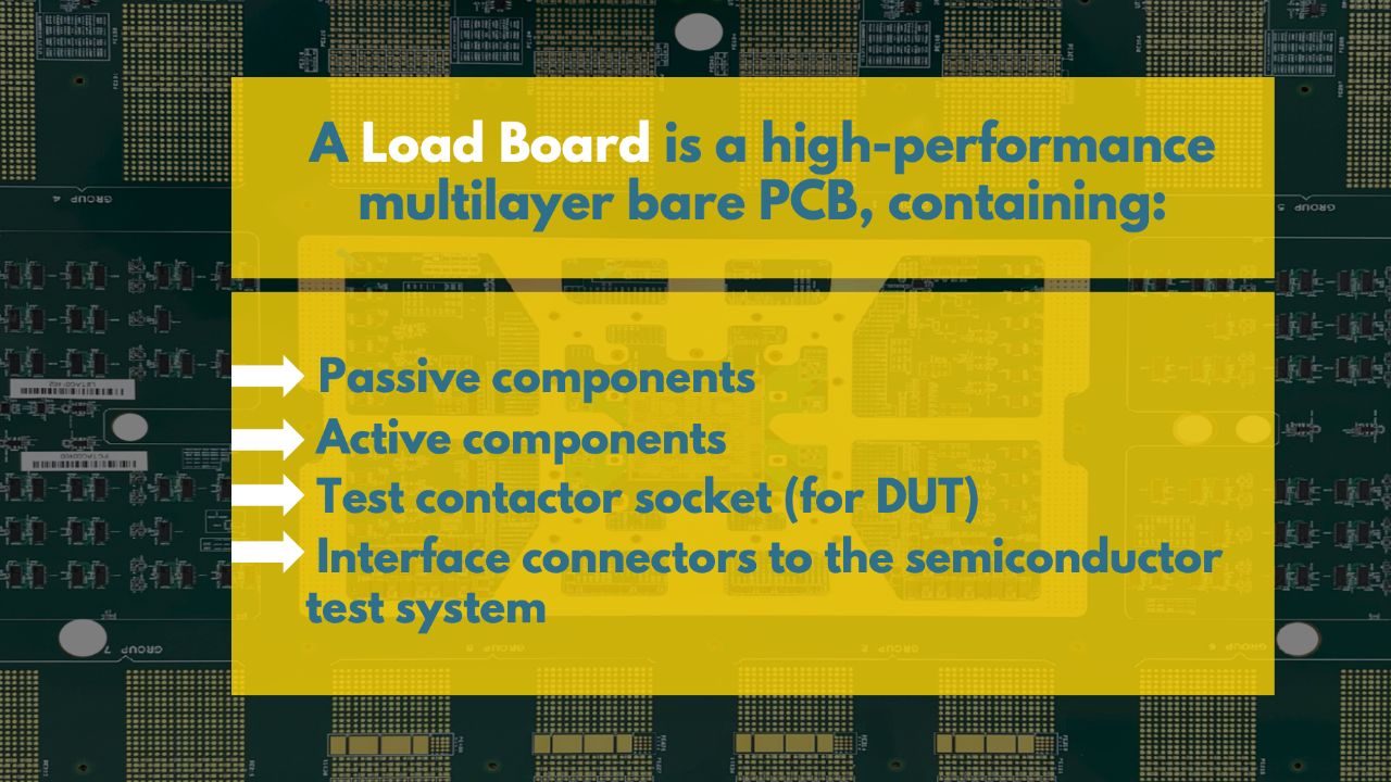
What is a Load Board?
A semiconductor load board is a high-performance, multi-layer circuit board used to test semiconductor devices during production. It is designed to interface with the semiconductor device and the test equipment to perform electrical tests on the device and verify its functionality, performance, and reliability. The load board provides a connection between the device under test and the test equipment, allowing for the application of electrical signals and measurement of device responses. It is an essential tool for semiconductor manufacturing, ensuring the quality and reliability of the devices before they are shipped to customers.
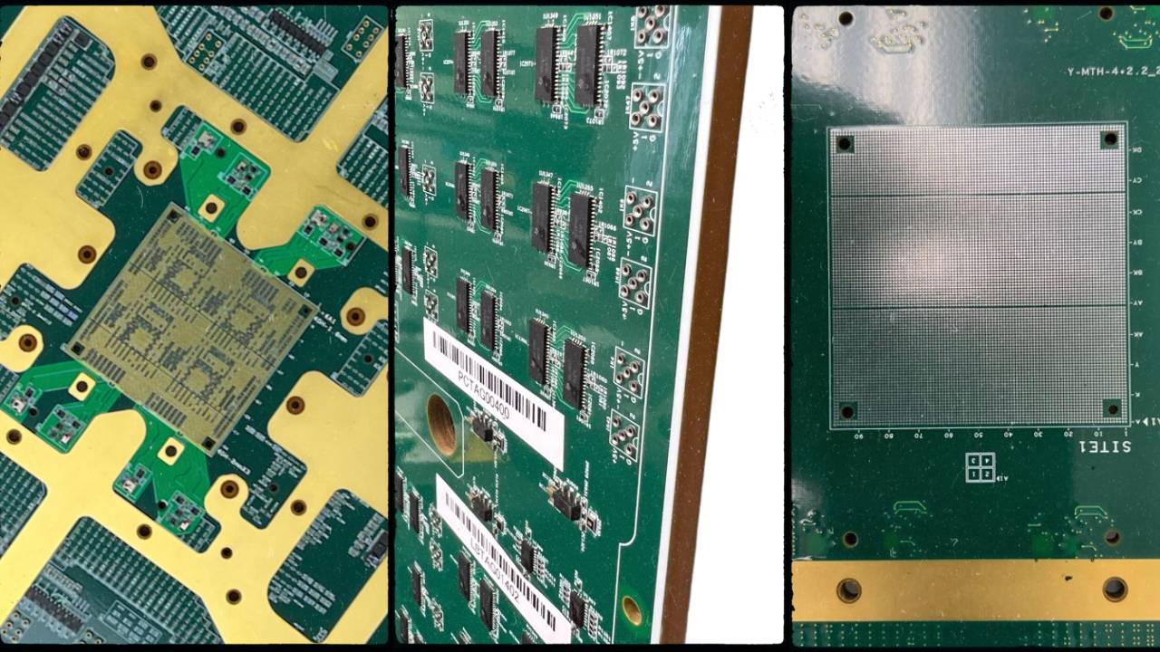
Load Board Complexity
Multi-DUT sites
Higher DUT pin count
Fast digital I/O speeds

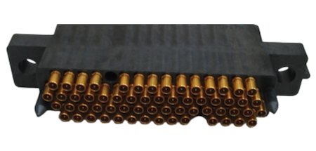
Load Board – Coaxial Connector Testing
Integrate mating Connector within Flying Prober to use for PCBA testing
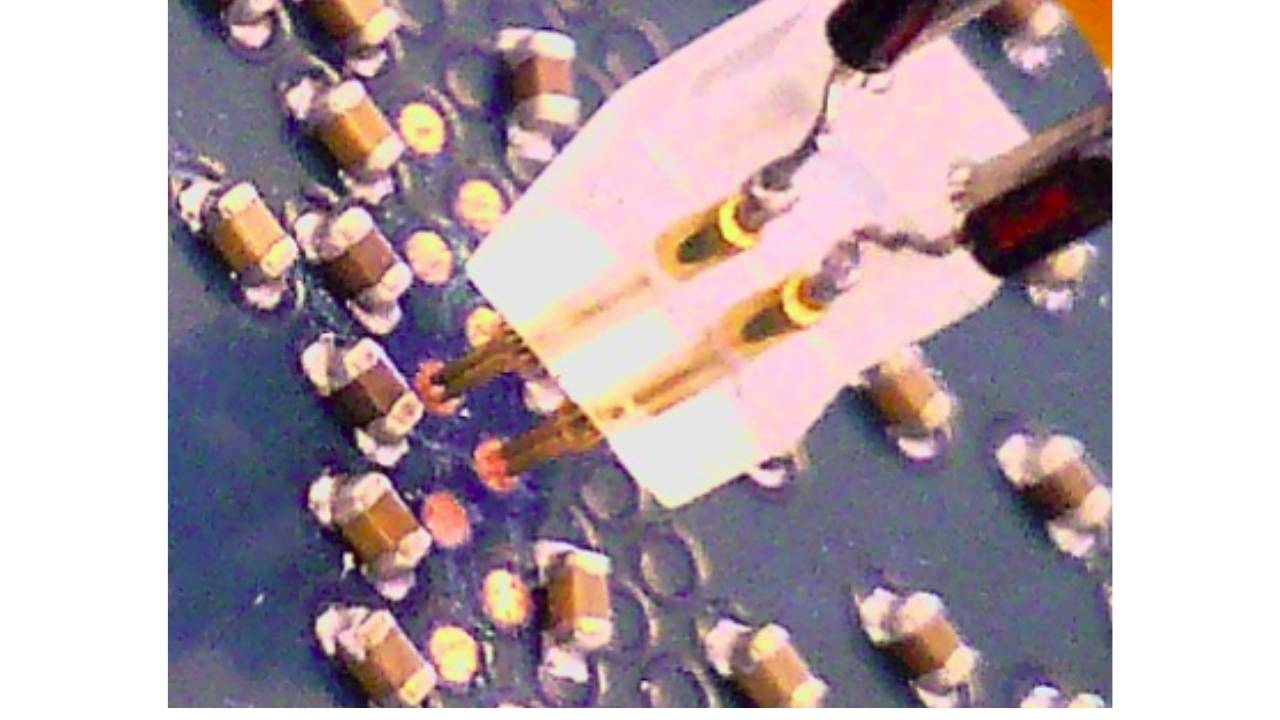
RF Testing
Measure frequencies up to 40Ghz with high precision placement on top and/or bottom side of PCBA.
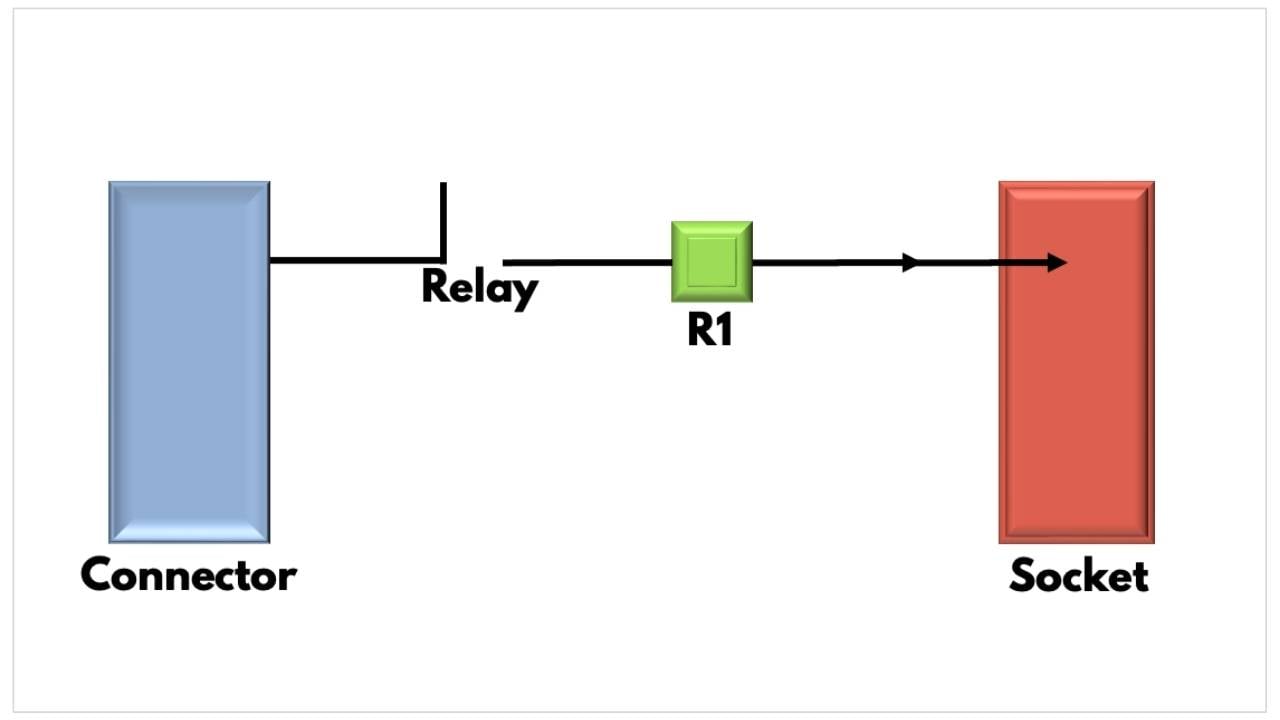
Channel Continuity Test
The DUT Channel Continuity Test verifies the entire signal path
To understand this test, we trace a Channel from the Input to the DUT.
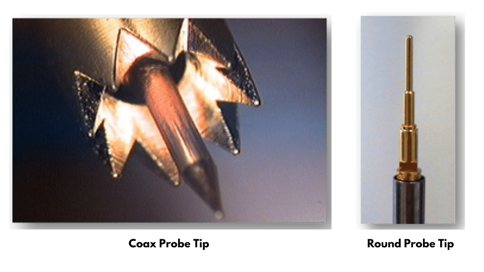
Load Board Safety
A variety of probe tips (and custom probe tips like the Coax Probe Tip for TDR measurement)
Programmable X, Y & Z axis
Programmable angle probing
Programmable probe speed0.75 – 0.015m/s
Test Point Balancing software ensures the Flying Scorpion system will not violate a user specified contact limit