
Introduction / Customer Challenge
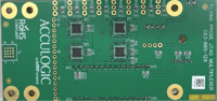
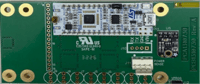 This project involved the design and development of a Flying probe JTAG Multiplexer (MUX) for previously delivered Flying probe systems. The customer required an upgrade that would enable routing of JTAG signals from the tester to the Device Under Test (DUT) without modifying the existing tester hardware. The primary objective was to provide a flexible and fully programmable JTAG routing solution that could support various test configurations while maintaining compatibility with the installed Flying probe platform.
Technical Challenges
The customer designed a standard 4×4(16-pin) grid on their boards to standardize the JTAG programming signals.
These signals had to be routed to any grid position in any combination and configuration. Key constraints included the need for full programmability, only four available wires between the tester and the external JTAG MUX, the inability to add additional wiring, and severe space limitations within the existing system.
Acculogic Solution
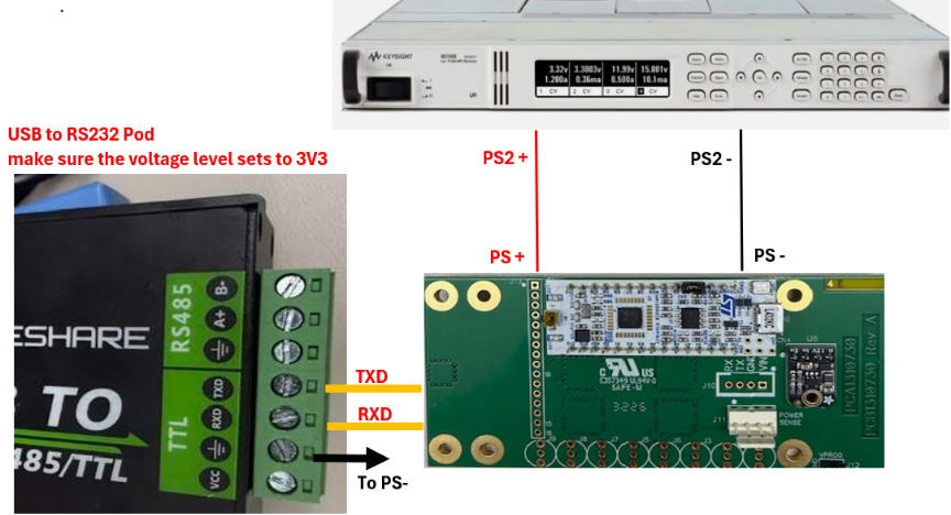
After evaluating multiple approaches, we determined that the existing system could provide only four connections between the tester and the JTAG MUX. To overcome this challenge, we implemented microcontroller-based architecture that communicates with the tester through an RS-232 interface. Two wires are used for RS-232 communication, and two wires provide power to the JTAG MUX. The microcontroller receives commands from the tester and dynamically reconfigures the signal routing using analog switches, providing complete routing flexibility while preserving the existing tester infrastructure.
Implementation Details
The selected controller was the STM32L432KC from STMicroelectronics and the signal routing was implemented using MAX14661 analog switch devices. Firmware was developed to continuously monitor RS-232 commands and translate them into switch-control instructions in real time. Communication between the STM32 microcontroller and the MAX14661 devices is performed through the I2C interface. Upon receiving a routing command, the firmware updates the switch configuration and establishes the required JTAG signal path without interrupting system operation.
Hardware Integration
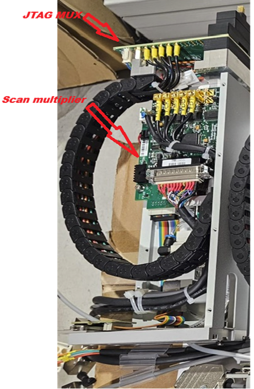 The completed module was integrated into the existing Flying probe system and consists of two main functional blocks: the Scan Multiplier and the JTAG MUX Module. The solution was designed to fit within the limited space available inside the tester without requiring mechanical modifications.
4 x 4 Routing Grid
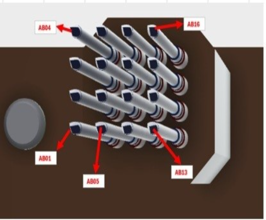
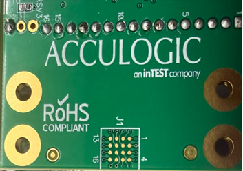 The JTAG MUX routes signals through a 4 x 4 matrix consisting of sixteen available connection points (AB01 to AB16). Any JTAG signal can be assigned to any grid location through software commands sent from the tester, eliminating the need for rewiring and allowing rapid adaptation to different DUT configurations.
RS-232 User Interface and Command Structure
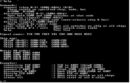
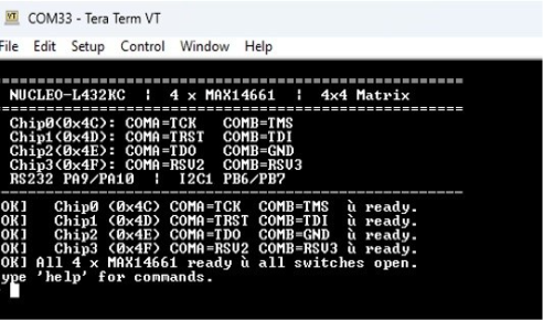 When the module is powered on, the firmware displays a welcome message showing the detected hardware, I2C communication status, current switch configuration, and system readiness. Routing commands can then be issued through a terminal application such as Tera Term. Example command: “connectsig TCK AB07”. This command connects the TCK signal to grid location AB07. The firmware immediately determines the required switch settings and programs the analog switches through the I2C interface.
Graphical Configuration Utility
To further simplify system configuration and improve usability, a dedicated graphical application was developed for the JTAG MUX system.
Instead of manually entering RS‑232 commands, users can assign JTAG signals to grid locations through an intuitive graphical interface. The application visually represents the 4 × 4 routing matrix and allows users to select signal-to-pin assignments using simple point-and-click operations.
Once the desired routing configuration is defined, the application automatically generates all required JTAG MUX commands and saves them to a command file. This file can then be executed by the tester software to configure the routing matrix automatically.
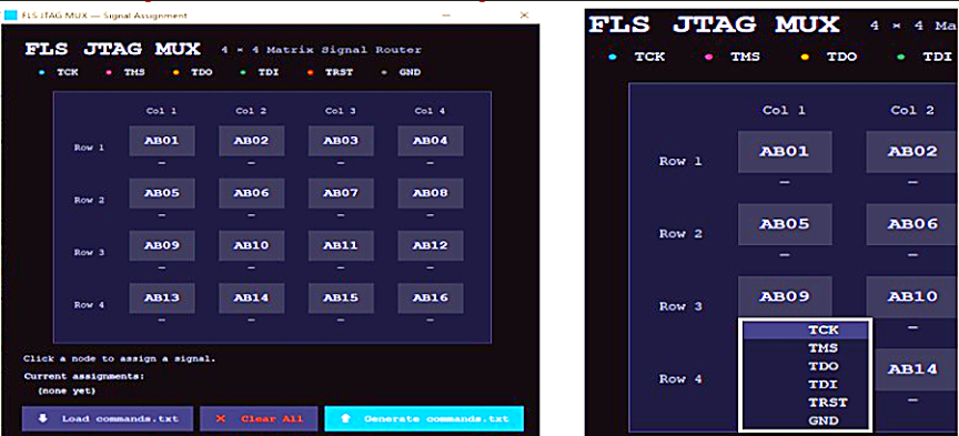
Key benefits of the graphical configuration utility include:
- Eliminates manual command entry.
- Reduces the potential for operator errors.
- Simplifies management of complex routing configurations.
- Enables rapid creation and modification of test setups.
- Improves usability for operators with limited knowledge of the underlying command syntax.
- Provides a repeatable and traceable method for storing routing configurations.
The graphical utility significantly enhances the overall user experience by allowing engineers to configure JTAG routing visually while automatically generating the corresponding RS‑232 command sequences required by the JTAG MUX firmware.
Example Workflow
- Launch the graphical configuration application.
- Select the desired JTAG signals (TCK, TMS, TDI, TDO, TRST, Ground, RSU2, or RSU3).
- Assign each signal to the required matrix location (AB01–AB16).
- Save the configuration.
- The application automatically generates the corresponding command file.
- The tester loads and executes the file to configure the JTAG MUX.
This approach allows complex routing configurations to be created in seconds without requiring users to manually construct individual commands such as:
System Operation
The JTAG MUX powers up and initializes the STM32L432KC microcontroller, verifies communication with all MAX14661 devices, displays a status message over RS-232, receives routing commands from the tester, programs the MAX14661 devices over the I2C bus, and establishes the requested signal path. The result is a compact, cost-effective, and fully programmable JTAG routing solution that satisfies all customer requirements while operating within strict space and wiring constraints.
General Application
The JTAG MUX can also be used in other applications that require signal routing within a voltage range of 1.8 V to 5 V. In addition to JTAG signal routing, it can be utilized with various programming and test systems that require multiple signals to be switched or routed between different devices.
Main Features of the Flying Probe JTAG MUX Card
- Fully Programmable JTAG Signal Routing
- 4 × 4 Routing Matrix (16 Connections)
- Microcontroller-Based Architecture
- RS-232 Communication Interface
- Analog Switch Routing Technology
- Compact Design
- Graphical Configuration Utility
- Wide Range Voltage Compatibility (1.8V to 5V)
- Cost-Effective Upgrade Solution
Conclusion
The Flying probe system JTAG MUX project successfully delivered a fully programmable JTAG routing solution for an existing FLS platform while operating within strict hardware constraints. Despite having only four available connections between the tester and the routing module, the implementation leveraged an STM32L432KC microcontroller, RS-232 communication, and MAX14661 analog switches to provide complete routing flexibility.
The solution enables dynamic assignment of JTAG signals to any position within the 4 × 4 grid, eliminating the need for rewiring and simplifying support for multiple DUT configurations. The compact design, seamless integration, and robust firmware architecture allowed the customer to upgrade their existing tester capability without significant hardware modifications, resulting in a cost-effective and scalable enhancement to the Flying probe system platform.